cadmeister-thai@uelthai.co.th
PHONE
096-9506570
cadmeister-thai@uelthai.co.th
096-9506570

DENKYOKU-CAD provides a full support for all phases of: creating mold, considerations and shaping of electrode parts, and creating documents in order to perform electric discharge.
DENKYOKU-CAD assigns the attributes unique to electrode to electrode shapes, and transfers the deliverables to DENKYOKU-CAM for further automatic processes.
Positions that require electrical discharge machining can be intuitively understood. As a result, operation errors are reduced.
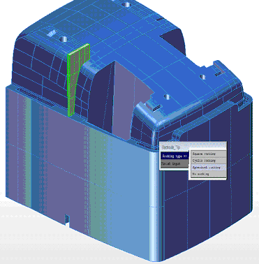
Electrode edges are shaped in accordance with 4 key shape patterns.
There are 3 standard patterns of electrode oscillating machining: circle, corner, or globe oscillation.
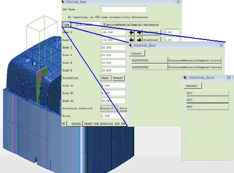
Optimum dimensions can be automatically calculated for pedestal shapes.
Or, they can be chosen from a standardized list (referred to as DB table) prepared by users.
Instruction documents in the form of spreadsheet can be output for electrical discharge machining by using highly responsive XVL data.
The instruction spreadsheets can be electronically viewed through the use of (free of charge) dedicated tool. Thus, human errors caused by prejudices can be reduced, due to 3D confirmations of the positions of electric discharge and electrode shapes.
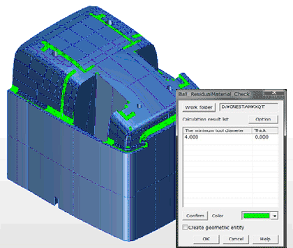
Interference Check
The interference situations between electrode models and modelled shapes can be visually confirmed through the use of Color Mapping Function.
Copy of Electrode Shapes
An electrode shape can be copied on a surface of placing the shape by executing commands for copying in parallel, by rotation or through the use of mirror effects (the "Copy_Parallel" command, the "Copy_Rotation" command, or the "Copy_Mirror" command), provided that the electrode shape has been created.
These commands can reduce the workload of considering and creating electrode shapes.
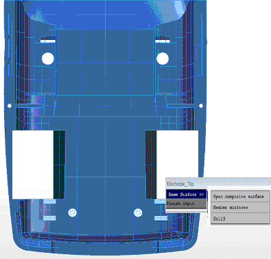
Standard Settings
2D datum references that are essential for electrical discharge machining can be visually set. (the "RefCorner" command)
Altitude datum references can be set intuitively due to 3D capabilities. (the "Change_EDM_Position" command, the "Electrode_SetBasePlane" command)
UEL (Thailand) Co.,Ltd.


 TH
TH IN
IN VN
VN